
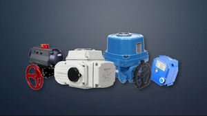

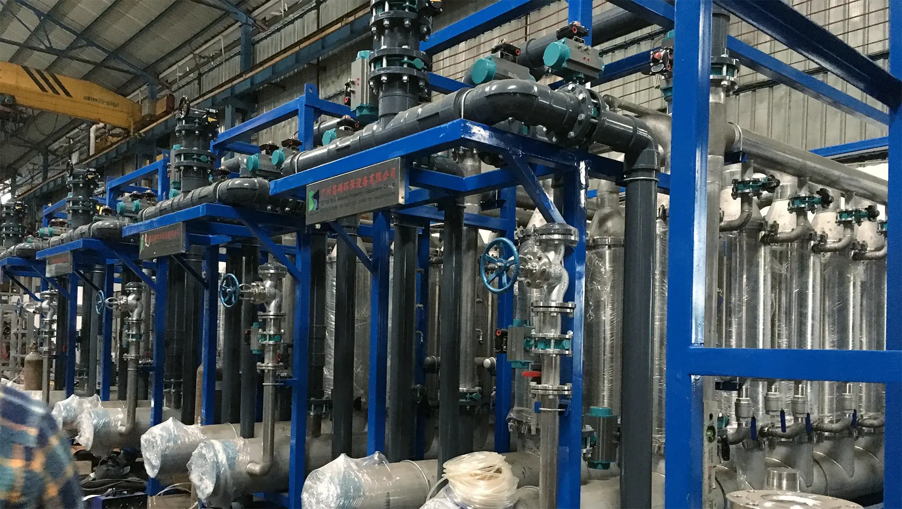
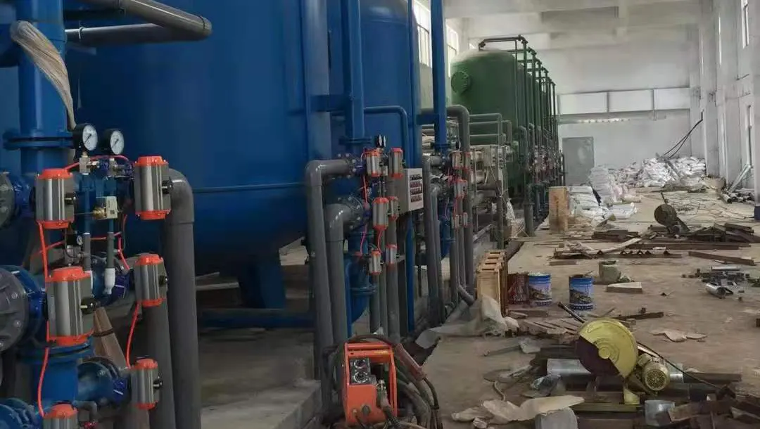
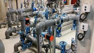

Pneumatic actuators is another name for pneumatic device, which is a device that translates the energy from a compressed air supply into a
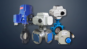
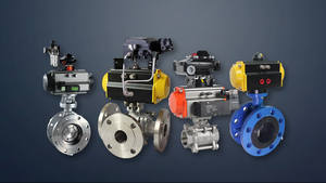
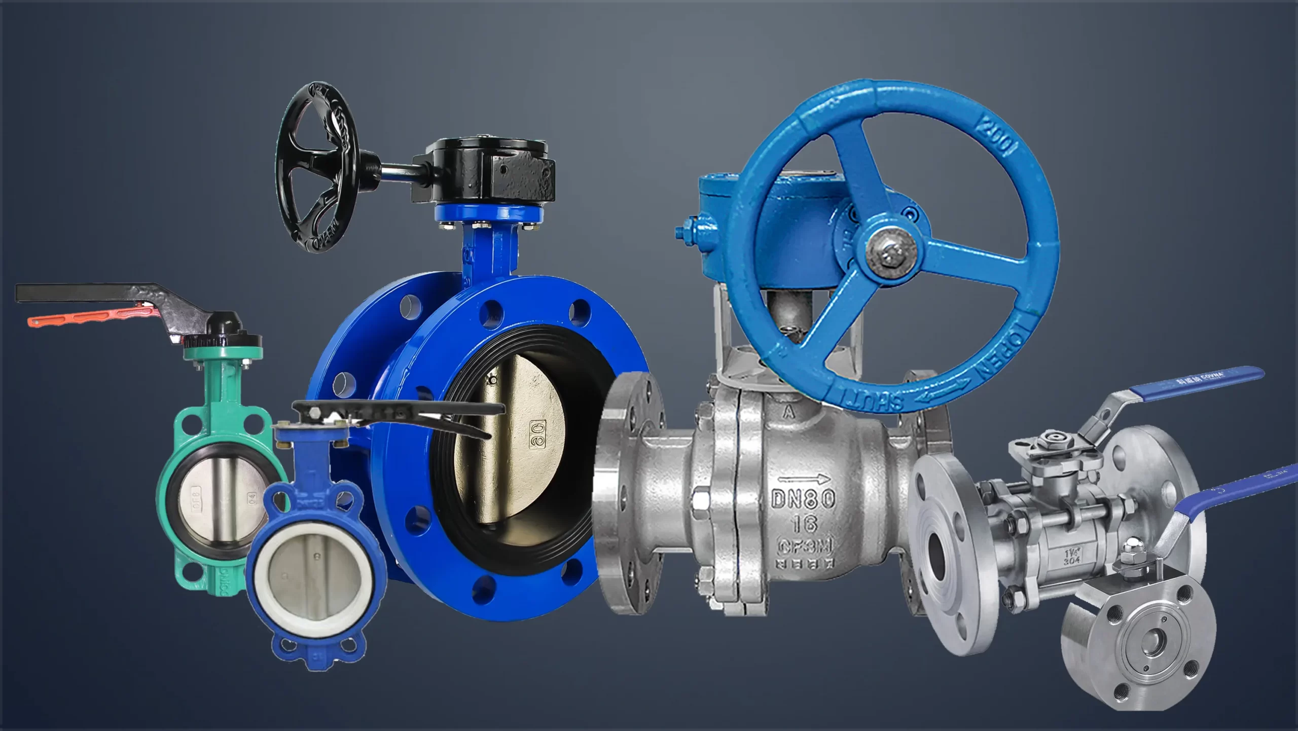
linear or rotary movement to open and close or modulate valves. This article describes the various technical requirements of the pneumatic actuator. COVNA pneumatic actuator with spring return & double return can be set on ball valves, butterfly valves.
Structure for Pneumatic Actuator:
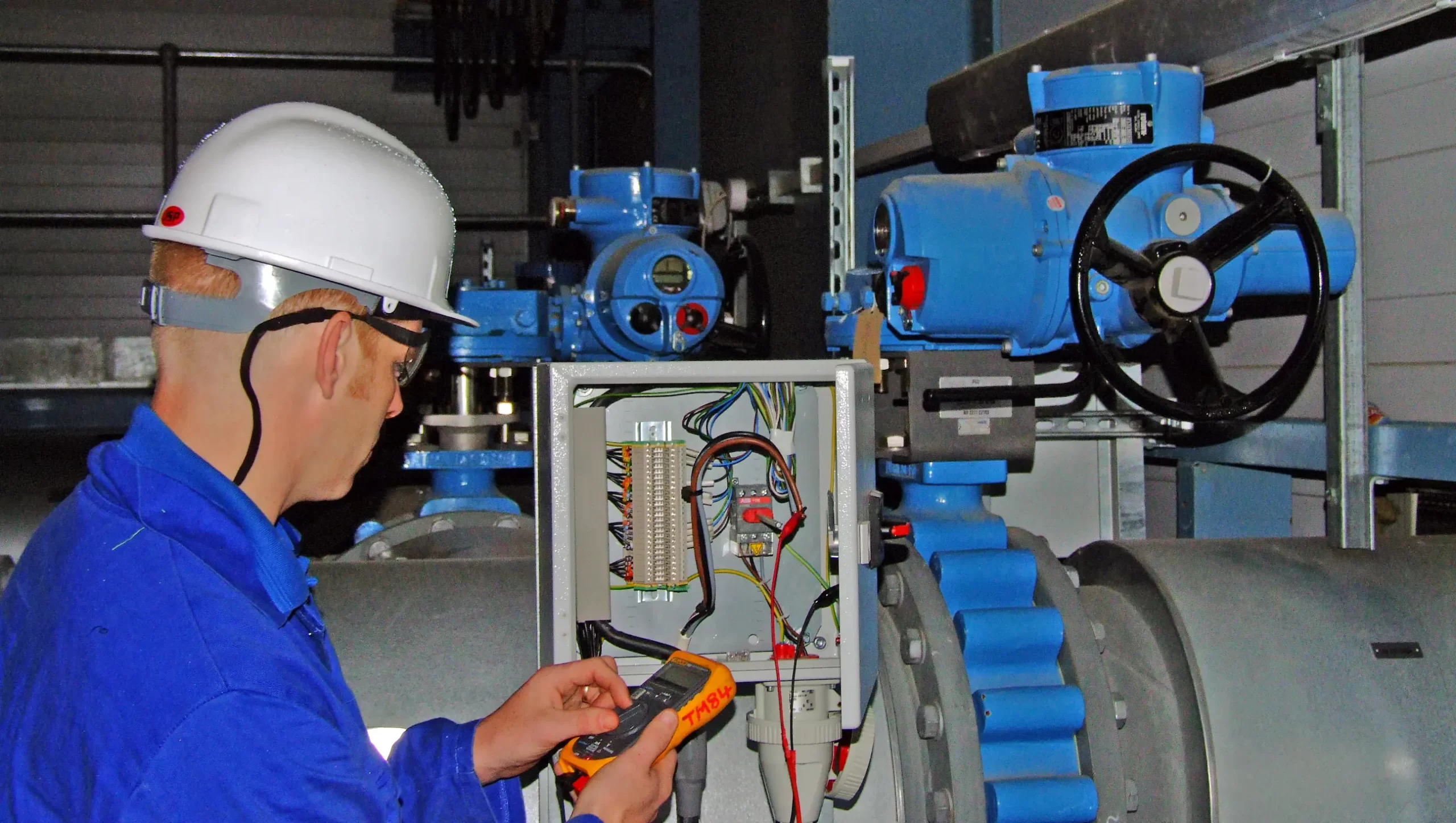
1. The pneumatic device should be composed of air cylinder, opening indication, stroke limit, pneumatic components, manual mechanism, signal feedback and other components.
2. The connection size of the pneumatic device and the valve should meet the requirements of GB/T12222 and GB/T12223.
3. The pneumatic device with manual mechanism should be able to use its manual mechanism to open and close the valve when the air source is interrupted. When facing the handwheel, the handwheel or handle should be turned counterclockwise to open the valve, and clockwise to turn the valve turn off.
4. When the end of the piston rod is internally or externally threaded, there should be a wrench mouth suitable for standard wrenches.
5. The sealing ring of the piston should be easy to replace and repair.
6. For pneumatic devices with buffer mechanism, the stroke length of the buffer mechanism can refer to the regulations in “Table 1”.
7. The pneumatic device with adjustable buffer mechanism should have a mechanism for adjusting the buffer function outside the cylinder.
8. The thread size of the air inlet and outlet of the cylinder should meet the requirements of GB/T7306.1, GB/T7306.2 and GB/T7307.
Performance:
1. The rated output force or torque of the pneumatic device should meet the requirements of GB/T12222 and GB/T12223
2. Under no-load conditions, input the air pressure specified in “Table 2” into the cylinder, and its action should be stable without jamming and crawling.
3. Under the air pressure of 0.6 MPa, the output torque or thrust of the pneumatic device in the opening and closing directions should not be less than the value indicated on the pneumatic device label, and the action should be flexible, and permanent deformation and Other abnormal phenomena.
4. When the maximum working pressure is used for the sealing test, the amount of air leaking from the respective back pressure side is not allowed to exceed (3+0.15D) cm3/min (standard state); leaking from the end cover and output shaft The air volume is not allowed to exceed (3+0.15d) cm3/min.
5. The strength test is carried out with 1.5 times the maximum working pressure. After the test pressure is maintained for 3 minutes, no leakage and structural deformation are allowed on the cylinder end cover and static seal.
6. The number of operating life cycles. The pneumatic device simulates the valve action. Under the condition of maintaining the output torque or thrust capacity in both directions, the number of opening and closing operations should not be less than 50000 (open-close cycle is one).
7. Pneumatic device with buffer mechanism, when the piston moves to the stroke end position, no impact phenomenon is allowed.
Surface and Appearance Quality:
1. There must be no scratches, cut marks, pores, burrs, etc. on the end cover, end flange and box of the cast cylinder.
2. The paint layer or chemical treatment layer on the outer surface of the pneumatic device should be flat, smooth, uniform in color, and free of oil, indentation and other mechanical damage.
Test Method for Pneumatic Actuator:
No-load test:
1. The pneumatic device is placed horizontally, and the air pressure specified in “Table 2” is alternately applied to both sides of the cylinder, and the exhaust side is open to the atmosphere, so that the pneumatic device is switched. The test results should meet the requirements of (Performance 2).
2. For the cylinder with buffer mechanism, the buffer valve should be fully opened during the no-load test.
Strength test:
Use a mixture of 70% kerosene and 30% spindle oil or compressed air as the medium, press 1.5 times the maximum cylinder working pressure (maximum pressure value allowed), alternately apply pressure to the cylinder, and keep the pressure for 3 minutes, then observe the cylinder Appearance and disassembly inspection, the results should meet the requirements of (Performance 5). When testing with air, safety precautions must be taken.
Load test:
Install the pneumatic device on the test bench, apply compressed air with a pressure of 0.6 MPa to the cylinder, and gradually apply torque or thrust to the output shaft. Measure the output torque or thrust of the pneumatic device at this time, and its value is not less than the requirements of the pneumatic device label value. At the same time, check the manual mechanism, opening indication, travel limit, information feedback and other components one by one, and the results should meet the requirements of (performance 3).
Sealing test:
Under no-load conditions, the pneumatic device alternately applies compressed air of 1.1 times the maximum working pressure from the two air inlets to check the air leakage at the piston and output shaft. Keep the pressure for 3 minutes, and the leakage should meet the requirements of (Performance 4). Another inspection method of the seal test: check the indicated pressure of the pressure gauge for 5 minutes, and the gauge pressure does not drop as qualified. Choose one of the two methods.
Operation life test:
Install the pneumatic device on the test bench, under the load of the rated output torque, simulate the opening and closing action process of the drive valve to perform cyclic operation until the output torque or thrust of the pneumatic device is less than the specified rated torque or thrust. The number of actions at this time is the life. frequency. The number of operating life should meet (Performance 6).
Inspection Rules for Pneumatic Actuator:
Type test (type test should be carried out if one of the cases on the right is present):
1. Trial-making appraisal of new products or old products transferred to factory production
2. When there are major changes in the design, process, production equipment, management, etc. of the normally produced product, which may affect the product performance
3. During normal production, a test should be performed periodically or after a certain output has been accumulated
4. When products that have not been produced for a long time resume production
5. When there is a big difference between the factory inspection result and the last type test
6. When the national quality supervision agency proposes to carry out type test requirements
Logo (the product label should be installed at the obvious part of the pneumatic device, and the label should meet the requirements of GB/T13306, and should indicate the content on the right):
1. Name of manufacturer
2. Product name and model
3. Output rated torque or thrust
4. Working pressure of cylinder
5. Product factory number
6. Date of manufacture
Package:
1. The pneumatic device should be shipped in a box and should be fixed in the box
2. The packing box should be firm and rainproof. There should be a clear mark that is not easy to erase on the surface of the packing box, and the content is:
a) Name and address of manufacturer
b) Product name and model
c) The name and address of the receiving unit
d) Contract number
e) Gross weight and volume (length×width×height
3. When the pneumatic device leaves the factory, it should be accompanied by a product certificate, product instruction manual, and packing list stamped by the inspector. The packing list should include the following:
a) Name and address of manufacturer
b) Product name, model, standard number
c) Product factory number
d) Product net weight
e) The accompanying documents, the name and quantity of spare parts
f) Packing quantity
g) Packing date
Store:
The product should be stored in a ventilated, dry and clean room
--- END ---
