
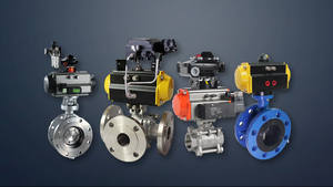
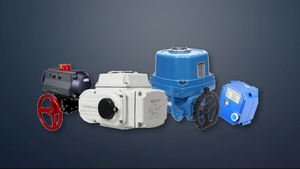


Electric actuators and pneumatic actuators, are an important part of the control system. It receives the 4-20mA or 0-10mA DC current signal from the controller, and converts it into the corresponding angular displacement or linear displacement, to manipulate the valve, baffle and other control mechanisms to achieve automatic control.
Electric actuators are available in linear, angular and multi-turn types.
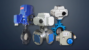
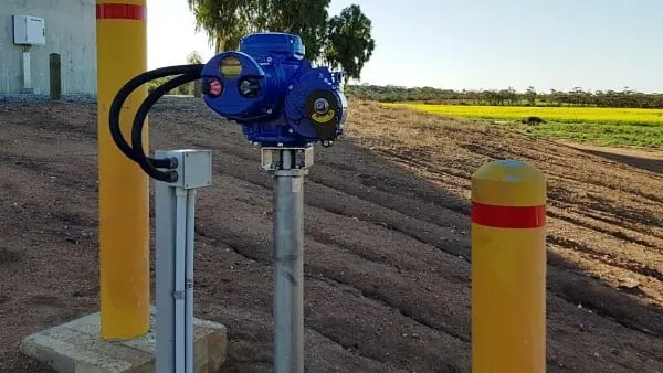
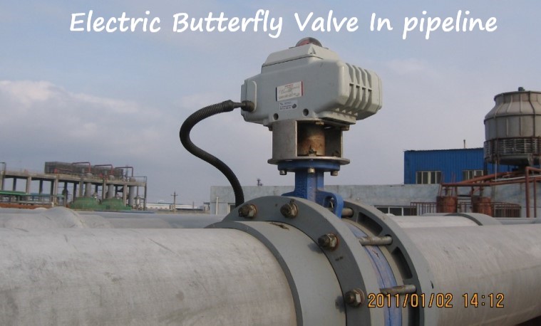
- The angular stroke electric actuator uses the motor as the power element to convert the input DC current signal into the corresponding angular displacement (0 degrees to 90 degrees). This type of actuator is suitable for manipulating rotary control valves such as butterfly valves and baffles.
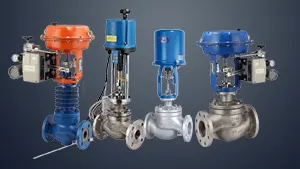
- The linear actuator receives the input DC current signal to make the motor rotate, and then it is decelerated by the reducer and converted into a linear displacement output to manipulate various control valves such as single-seat, double-seat, three-way, and other linear control mechanisms.
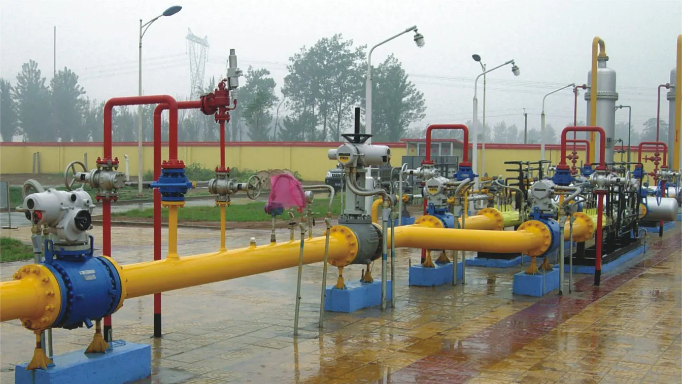
- Multi-turn electric actuators are mainly used to open and close multi-turn valves such as gate valves and globe valves. Because of its relatively large motor power, the largest is tens of kilowatts, and it is generally used for local control and remote control. These three types of actuators are all position servo mechanisms powered by two-phase AC motors. The electrical principles of the three are exactly the same, but the reducer is different.
The main performance indicators of the quarter-turn electric actuator:
Three-terminal isolated input channel, input signal 4-20mA (DC), input resistance 250 ohms; output torque: 40, 100, 250, 600, 1000 N·m; basic error and variation are less than ±1.5%; sensitivity 240μA.
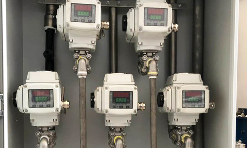
The Electric Actuator is mainly composed of a servo amplifier and an actuator.
The operator can be connected in series. The servo amplifier receives the control signal from the controller and compares it with the feedback signal of the output displacement of the electric actuator.
- If there is a deviation, the difference is after the power is amplified, the two-phase servo motor is driven to rotate. Then the speed reducer will drive the output shaft to change the rotation angle. If the difference is positive, the servo motor rotates forward and the output shaft angle increases;
- If the difference is negative, the servo motor reverses and the output shaft angle decreases. When the difference is zero, the servo amplifier outputs a contact signal to stop the motor, and at this time the output shaft is stabilized at the corner position corresponding to the input signal. This kind of position feedback structure can make the linear relationship between input current and output displacement better.
The electric actuator can not only cooperate with the controller to realize automatic control, but also realize the mutual switching between automatic control and manual control of the control system through the operator. When the switch of the operator is placed in the manual operation position, the power supply of the motor is directly controlled by the positive and negative operation buttons to realize the forward or reverse rotation of the output shaft of the actuator for remote manual operation.
How the position transmitter works?
The function of the position transmitter is to linearly convert the displacement of the output shaft of the electric actuator into a feedback signal, which is fed back to the input of the servo amplifier.
The position transmitter usually includes two parts: displacement detection element and conversion circuit.
- The displacement detection element is used to convert the displacement of the output shaft of the electric actuator into signals such as millivolts or resistance. Commonly used displacement detection elements include differential transformers, plastic film potentiometers and displacement sensors;
- The conversion circuit is used to output the displacement detection elements The signal is converted into the signal required by the amplifier, such as a 0-10mA or 4-20mA DC current signal.
How the servo amplifier works?
The servo amplifier mainly includes an amplifier and two sets of thyristor AC switches.
- The function of the amplifier is to compare the input signal and the feedback signal to obtain the difference signal, and according to the polarity and magnitude of the difference, control the on or off of the thyristor AC switch.
- The thyristor switch is used to switch on the AC power supply of the servo motor to control the forward and reverse rotation of the servo motor or stop non-rotation respectively.
What’s the function of servo amplifier?
The function of the servo amplifier is to compare, amplify and calculate the input command signal (voltage) with the system feedback signal (voltage), and then output a control current proportional to the deviation voltage signal to the servo valve torque motor control coil to control the servo valve spool The opening is large and small, and plays a role of limiting protection.
--- END ---
